Table of Contents
Growing CNTs by chemical vapor deposition
Physical deposition of catalyst
Electron beam evaporation of pure iron is an excellent way to deposit catalyst. If a thin layer is used (0.1 -0.4 nm) then you can grow exclusively single wall CNTs. We use the recipe published by the Rogers group (Nature Nanotech 2007). It is useful to look at the McEuen group's version of this recipe.
A 0.2 nm layer of Fe is invisible when you inspect the chip by naked eye, but you can see the iron in an AFM (image below). The Fe layer will bead up on the surface at high temperature and yield nanotube tube diameters < 2 nm.
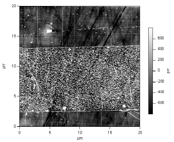 | Figure: 20×20 micron AFM scan showing CNTs growing from a stripe of evaporated iron (10 microns wide and 0.1 nm “thick”) deposited on ST-cut quartz. Patterning was done by photolithography. Nanotubes can be seen growing above and below the iron stripe. Growth direction is perpendicular to the wafer flat. |
Paint-on catalysts
We have tried at least four different iron-based catalysts that are suspended in a solvent. Even more variations exist in the literature. The alumina supported catalyst is tried and true:
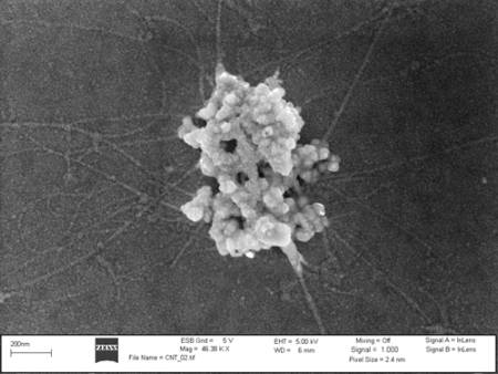 | Figure: SEM image of CNTs growing from alumina supported catalyst. Scale bar is 200 nm. The advantage of alumina supported catalyst is the high surface area of the alumina. The high surface area leads to more nanotube nucleation sites. One disadvantage is that alumina nanoparticles, together with sticky nanotube grass, stick to the AFM tip during imaging (it is best to avoid imaging directly over the alumina!). A second disadvantage is that the diameter distribution of CNTs tends to be broad. |
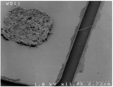 | This image comes from Ethan Minot's PhD thesis (Fig. 3.2). The alumina supported catalyst is patterned in a 4 x 4 micron square. Hundreds of CNT grow inside the 4 x 4 square, making it look like a bird's nest. |
- Alumina supported catalyst. The original recipe for this catalyst was published in Nature in 1998 (Kong et al.). Kong used methanol as the liquid instead of DI water, but methanol is not compatible with photoresist patterning (methanol is compatible with ebeam resist). Other groups (for example, Cees Dekker's group) have used isopropanol as the liquid. I don't know if the choice of liquid makes a difference. The original recipe from Kong et al. also has an additional baking step after solution deposition which many groups now skip. Here is a water-based recipe (compatible with photoresist) that was developed in the McEuen group:
- 60 mg Fe(NO3)3•9H2O * see the suggestion below
- 15 mg MoO2(acac)2 * see the suggestion below
- 45 mg Al2O3 (Alumina)
- 45 mL DI water
- Stir (10 min with magnetic stir rod) and then sonicate several hours when first made, should look red ()
- * Suggestion Our current formula has four times as much Iron Nitrate and Molybdenum Acetate as the preceding formula. This was done to increase our return on the number of nanotubes. We know the new formula does grow tubes, but it does not look like it makes more tubes than the recipe at lower concentrations like we hoped. Another potentially important difference is that we are using Mo(acetate)2. Where Mo is in the 2nd oxidation state. The MoO2(acetate)2 is in the 6th oxidation state. We tried growing tubes using a solution made exclusively of of Mo(acetate)2 and alumina. We did not find any tubes grown using this solution. So it looks like all tube growth (so far) is due to either Fe or an FeMo alloy.
- Iron nitrate solution
- Mix 60 mg Fe(NO3)3•9H2O, clean with 45 mL DI or IPA (concentration calculation). When working with a water based catalyst there are some additional considerations.
- Ferritin solution
- Always keep bulk supply of Ferritin in the fridge at ~ 4deg C
- Dilute bulk supply at least 1:100 in DI water (Josh has details)
- To get a reliable and uniform distribution of Ferritin the solution should be spun onto the chip and the chip should be pre-treated to get a hydrophilic surface.
- Iron nitrate solution thickened with PVP for use with spinner.
- Matt has had success with this catalyst.
- PEI Fe-Co cluster catalyst
- This is the most recent addition to our arsenal (thanks to Heather Wilson for fine tuning). The PEI is a negatively charged polymer that forms an agglomerate with a few hundred Fe3+ and Co2+ ions.
- 0.1 mg PEI, 0.2 mg Iron Nitrate, 0.14 mg Cobolt Nitrate mixed with 100 mL of DI water.
- Anything below 10 mg is hard to weigh on the scale - it is recommended to make concentrated solutions of each precursor and then use a micropipette to draw the appropriate volume of each ingredient.
- Cover the whole chip with a bubble of the solution, let soak for 8 minutes. N2 blow dry, DI H2O rinse, N2 blow dry.
- Open air anneal at 800C for 10 minutes prior to growth. The growth will still work without the anneal, but the yield and tube lengths are smaller.
1" Furnace growth
The CVD furnace uses quartz tubing to contain the gas flow while everything (chip, catalyst, gas) is heated to high temperature. We have spare quartz tubes in the event that the tube becomes contaminated. The quartz tube can become contaminated with carbon soot due to alcohols that have evaporated and condensed into the gas lines. To avoid this problem, the gas lines must be purged at low temperature prior to the growth process.
Recipes
*UPDATED 2022 by Dublin
(Click here for other recipes) and old_recipes
1" Furnace growth
Startup/Loading chips
- Keep chips ready for growth in furnace
- PNF are for Utah
- PNF - 2 micron trench
- PNR - 2.6 micron trench
- To pressurize:
- Connect hand pump to nipple
- Black button releases pressure
- Pump up to 25 in Hg
Ethanol/methanol levels: Use around half as much Methanol as Ethanol. (In my experience, a 1:1 ratio produces more multi-tube sites and shorts, so this ratio is important. - Dublin)
- Fill out logbook
- Always run purge
- STD growth
- Humidity
- Turn on Dehumidifier
- Humidity should be around 30%
- Check end cap is secure
- Check Ar and H tanks
- 20PSI on both
- Lose around 5psi of argon tank pressure per hour of flowing
- Load in chips. (I have successfully grown 3 at a time, which is all you can fit on the boat. - Dublin)
- Unscrew the end part
- Careful not to drop it
- Attach magnet to end of tray and slide in chip
- Reattach end part
- Current tube 2022: “Tristan”
Growth Process
Input purge parameters:
Anneal:
- 30 C
- 3 min
- Hydrogen: 0.45 SLM
- Argon: 1SLM
Transition:
- 0 min (no transition)
Growth:
- 30 C
- 3 min
- Hydrogen 0.45 SLM
- Methanol 0.3 SLM
- Ethanol 0.15 SLM
- Set timer for 5 min and start purge. Will go through anneal and “growth” stages at 30 C
- When changing parameters, give the program a few seconds to get it
- After purge finishes, reinitialize parameters
- Wait until all flow rates show zero
Growth Parameters:
Anneal:
- 800 C
- Hydrogen: 0.45 SLM
- 1 min
Transition:
- 0 min ramp time
Growth:
- 800 C
- 5 min
- Hydrogen 0.45 SLM
- Methanol 0.3 SLM
- Ethanol 0.15 SLM
- Start growth and set a timer for 14:30. When the furnace reaches 798 C, slowly and deliberately slide in tubes
- Once anneal phase begins, set timer for 4:30 min
- To check if it’s working: Ethanol and methanol are bubbling.
- When PID controller clicks off (growth is finished):
- Pull chip to rim of insulating chamber and allow to sit until 790 C
- Pull chip fully out
- When temp is 500 C, open lid
- When temp is 200 C or lower, pull out chip
- The program flows argon before 200C
- Close lid
- Unscrew end connector
- Drag magnet as far to the left as possible
- Grab back end of sled and pull chip straight out
- Grab in center of rod
- Keep the chip level! It’s not connected
- Place chip on beta wipe
- Hold rod while grabbing chip and place chip in holder
- Store rod in quartz tube, cap it up
- Screw end cap back on and seal tube
- Once chamber is cooled back down to room temperature, ready for another growth
4" Furnace growth
Updated 04-16-2013 by Heather
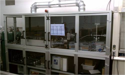
The 4“ growth system primarily differs from the 1” system in two ways. First, the larger diameter quartz tube allows for growth on larger substrates (growth on 3“ silicon wafers is possible). Second, the 4” furnace can be operated under vacuum, allowing for the growth of graphene as well as carbon nanotubes. The 4“ CVD furnace uses quartz tubing to contain the gas flow while everything (chip, catalyst, gas) is heated to high temperature.
Before using the system:
- Be sure that you understand the dangers and risks before attempting to use the growth system.
- Undergo a formal training session with either Jenna or Josh.
- You are thoroughly familiar with the standard operating procedure (below).
When using the system always adhere to the standard operating procedure.
Standard Operating Procedure
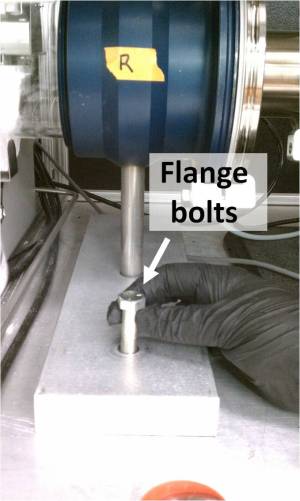
- Make sure the bolts are secured in the flange stands
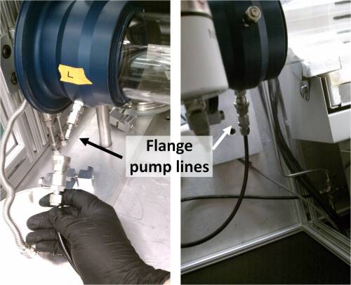
- Verify that the flange pumps are hooked up.
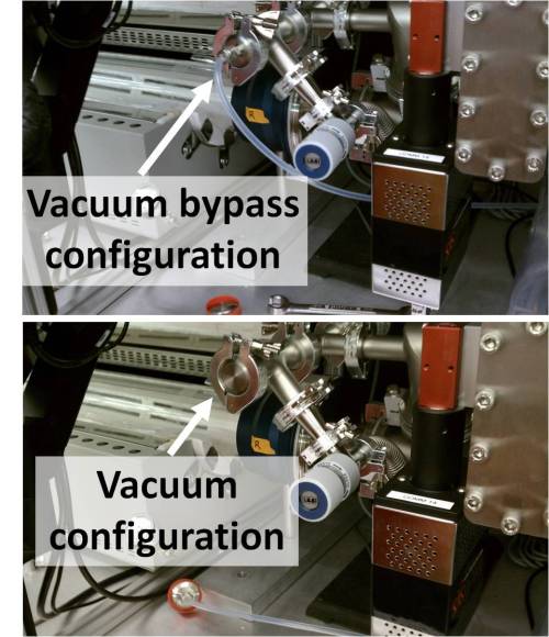
- If you will be doing a growth at atmospheric pressure, ensure that the system is in vacuum bypass configuration.
- The vacuum bypass line is hooked up
- The Intellisys device is closed: go to the “Graphs” tab of the furnace program and put 0.00 in the ”% open“ box, press enter.
- If you will be doing a growth under vacuum, ensure that the system is in vacuum configuration.
- The cap is in place rather than the vacuum bypass line
- The IntelliSys device is open: go to the “Graphs” tab of the furnace program and put 100.0 in the ”% open“ box, press enter.
- Insert your sample into the middle of the tube
- For open air anneal: leave the left end cap off and enter the following into the furnace program:
- Stage 1:
- Zone 1 Temp: 30C
- Zone 2 Temp: 800C
- Zone 3 Temp: 30C
- Duration: 10 min
- Un-check all gases, check the “off” boxes where applicable, and enter 0.0 for all gas flow rates.
- Other Stages:
- Enter 0 for temperatures, duration, gas flow rates and un-check all gases.
- Click the Update Recipe button, then click the Start button
- Allow furnace to cool to 200C - this takes about 2 to 3 hours. You may open the lid at around 500C to speed up cool down.
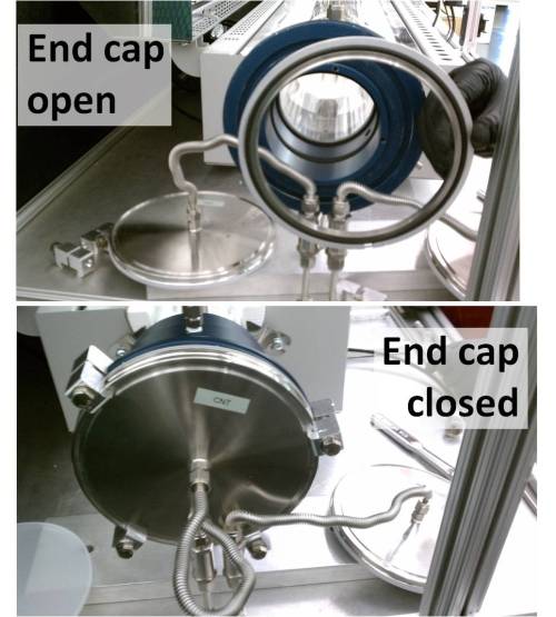
- Securely cap the end of the growth tube with the appropriate CNT or Graphene end cap.
- In the furnace program, click the appropriate CNT or Graphene button on the left.
- If you are doing a growth under vacuum, click the Turbo Pump button.
- For methane CNT growth at atmospheric pressure: enter the following growth recipe into the furnace program. (See notes at the end if you want to use a different recipe or modify this one.)
- Be sure to select and enter flow rates for gases with the CNT designation. Your gases will not flow if the wrong ones are selected!
- Stage 1: (purge part 1)
- Zone 1 Temp: 30C
- Zone 2 Temp: 30C (or whatever your current furnace temperature is at up to 200C)
- Zone 3 Temp: 30C
- Duration: 15 min
- Argon (CNT) 1.9 SLM
- Stage 2: (purge part 2)
- Zone 1 Temp: 30C
- Zone 2 Temp: 75C (or whatever your current furnace temperature is at up to 200C)
- Zone 3 Temp: 30C
- Duration: 10 min
- Argon (CNT) 0.5 SLM
- Hydrogen (CNT) 1.0 SLM
- Methane (CNT) 0.5 SLM
- Stage 3: (ramp under hydrogen)
- Zone 1 Temp: 30C
- Zone 2 Temp: 899C
- Zone 3 Temp: 30C
- Duration: 1 min
- Hydrogen (CNT) 1.0 SLM
- Stage 4: (growth)
- Zone 1 Temp: 30C
- Zone 2 Temp: 900C
- Zone 3 Temp: 30C
- Duration: 10 min
- Hydrogen (CNT) 0.125 SLM
- Methane (CNT) 1.5 SLM
- Stage 5: (cool down under Argon)
- Zone 1 Temp: 30C
- Zone 2 Temp: 200C
- Zone 3 Temp: 30C
- Duration: 1 min
- Argon (CNT) 1.9 SLM
- Click the Update Recipe button after the recipe has been entered.
- Click the large Start button at the top to start the program.
- Go to the Graphs tab to view the current status of your gas flow rates, time remaining per stage, and internal pressure.
- At the end of your program, click the large Stop button. The Argon safety gas should begin to flow until the furnace temperature reaches 200C. Stage 5 in the recipe above is entered to ensure that the Argon gas does flow during cool down.
- If you are modifying the recipe above, or using a different growth recipe, please read the following notes:
- Important: You must purge the tube at low temperature (less than 200C) for at least 25 minutes at a total flow rate of about 2 SLM prior to a growth.
- The duration of the purge is not typically a concern in the 1” furnace because the 1“ quartz tube is only about 0.5 L in volume. At a flow rate of 1 SLM, the entire gas content of the 1” tube is cleared every 30 seconds. The 4“ tube, however, has a volume of approximately 12 L. At a flow rate of 2 SLM, the volume is cleared only once every 6 minutes. Excess oxygen with hydrogen, methane, and/or ethylene at high temperatures can result in an explosion.
- Do not enter more than one stage in a row with temperatures below 100C. The furnace tends to overshoot the temperature, and the program will not proceed to the next stage within a reasonable amount of time (temperature will be too high, cool down is slow).
- For atmospheric pressure growths: In the stage after the final stage of your desired furnace program, select Argon for CNT or Graphene as appropriate, and enter a 1.9 SLM flow rate. Set temperature here to 200C, and enter 1 minute for the Duration. This is to protect your sample while the furnace is cooling down. (There is presently a bug in the program, the safety gas does not always automatically flow while cooling down.)
- The gases in the first stage will begin flowing after the entered temperature has been reached. In the subsequent stages, the gases of the next stage will begin to flow as soon as the previous stage is complete (before the next temperature is reached).
- Anytime you attempt a new recipe, you should babysit the furnace to make sure that the program proceeds the way you expect it to. The furnace program has a few bugs.
Leak checking
Leak checking is suggested every time the growth tubes are switched. Leaks during growth can result in bad yeilds and low growth, or, in a worst case scenario, an explosion.
- Make sure the flange bolts are secured in the flange stands.
- Verify that the flange pump lines are hooked up.|
- Cap the end of the tube with the appropriate CNT or Graphene end caps, ensure the bolts are tight.
- Be sure that the system is in vacuum configuration.
- Open the Intellisys device by entering 100% in the % open box at the bottom right corner of the Graphs tab in the furnace program.
- Go to the Lab View furnace program and click either the CNT or Graphene buttons as appropriate.
- Click the Turbo Pump button. Wait 5 minutes. The pressure should read approximately 100 μTorr or lower after 5 minutes.
- Click the Turbo Pump button to turn off the pump.
- Click the small red stop button on the tool bar of the furnace program at the top
- This is not to be confused with the emergency stop button
- Go to the Valve Pressure Reader LabVIEW program and click the run (arrow) button on the tool bar.
- Select either the CNT or Graphene button as appropriate.
- Enter 0.01 for the re-pressurization rate to start with, click the Pressurize button. You may increase the rate up to 0.05 or 0.1 as long as the Turbo Pump sounds like it’s handling it okay.
- When the pressure reads ~1 Torr, click the pressurization button again to turn off. Click the red stop button on the tool bar to stop the LabVIEW program.
- Slowly open the cap to finish re-pressurizing the tube. If you will be doing a vacuum growth, ensure that the system is in vacuum configuration. If you will be doing a growth at atmospheric pressure, ensure the system is in vacuum bypass configuration and enter 0.0% in the % open box in the Graphs tab of the furnace program.
- Go back to the furnace program, click the run (arrow) button on the tool bar to reactivate the furnace program.
Using the RGA
The residual gas analyzer (RGA) allows you to monitor the partial pressures of individual gases in the growth chamber.
Setting up the program
- Go to the RGA program.
- Under the Mode menu, select Histogram. Then go to Split under the Mode menu, select P vs T.
- Go to the Scan Menu, select Scan Parameters.
- In the top window, enter 1 for the Start Mass, and 70 for the Stop Mass. Click Apply in the same window.
- In the bottom window, enter the names and masses of the gases you would like to keep track of during the duration of the growth. Make sure the Enable checkboxes are checked for each gas. Click the Apply button in that window.
- It is suggested that you enter at least these gases: Nitrogen (28amu), Oxygen (32amu), Hydrogen (2amu), Water (18amu), Carbon Dioxide (44amu), Proton/H+ (1amu), Methane (16), Argon (40amu), and Helium (4amu).
- The bottom window sets up the P vs T graph. The P vs T graph does not differentiate between gases of the same atomic mass. For example: carbon monoxide, nitrogen and ethylene all have the same atomic mass (28amu). The P vs T graph is primarily useful for viewing the general trends and history of the gas concentrations. The histogram only displays the most recent gas concentrations during the growth.
- Go to the Scan menu, then to Schedule. Select the Triggered radio button, enter 120 seconds in the Trigger Every box. Click Apply.
- Go to the Graph menu, Select Scale, make sure Log is checked.
- Go to the File menu, then to Scan Logging. Enter 1 in the Save Every box, and enter 0 in the Max Saved box.
- Under Log File Name, select the User defined + Time Stamp radio button and enter a file name in the box.
- Go to the Log Dir button and select the file path. Make sure the Enable Scan Logging box is checked.
- Go to the Utilities menu, make sure the Analyze item is checked (click if not).
- Go to Analyze Settings. Review the default gases that are checked, and then double click any other gases that will be flowing during your growth.
- Click Apply.
- Under the Utilities menu, select Analyze Window.
Turning on the RGA
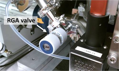
- Make sure the RGA valve is closed.
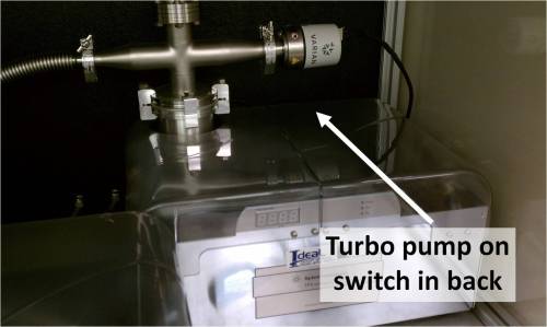
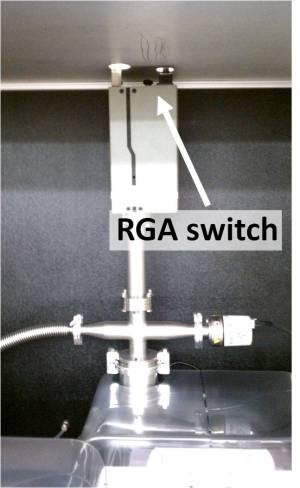
- Turn on the Turbo Pump and wait until the pressure reads 100 μTorr or lower. Then turn on the RGA head.
- In the RGA program: Click the Connector List Setup button on the tool bar (green button towards the right), select Comm 11 and click Connect.
- Verify the turbo pump pressure reads 100 μTorr or less. Click the Filament button on the tool bar (squiggly wire button) to turn on the filament. Then click the green Go button on the tool bar.
- WARNING Do not turn on the filament until the chamber pressure is 100 μTorr or less.
- Open the RGA valve, make sure the leak rate knob displays 100.
Turning off the RGA
Accessing saved RGA files
- Go to the Mode menu and select Histogram.
- Go to the File Menu and select Open Scan Logs, select your file.
- Go to the Utilities Menu, select Analyze Window.
- Use the green arrow buttons on the tool bar to scroll through your graphs.
Gas purities
Gases are ordered from Industrial Gas and Welding Supplies, Corvallis:
- Methane: “Chemically Pure Minimum Purity” 99.0% Airgas Part #: ME CP300
- Hydrogen: “Ultra High Purity Minimum Purity” 99.999% Thc < 0.2 PPM Airgas Part #: HY UHP300
- Argon: “Ultra High Purity Minimum Purity” 99.999% Thc < 0.5 PPM Airgas Part #: AR UHP300

