Microfluidics
The journal “Lab on a Chip” published a useful PMDS tutorial. This is Tal's preferred method of working with PDMS.
Bo Sun's research group at OSU frequently uses PDMS. They can also offer tips and tricks.
The “exhaust lines” should be big, so there is no back pressure on the system.
Nice trick for flow calibration: Collect the “exhaust” in a petri dish that is covered with parafilm (the parafilm stops evaporation). Weigh the petri dish before and after.
Laminar flow cell
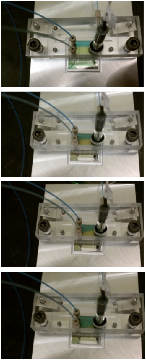
Tal developed this flow cell during his PhD. It is closely modeled on a flow cell developed at TU Delft by K.M. Hooning. Hooning's thesis is available on the T: drive. The sequence of images below shows blue dye and yellow being pumped through the flow cell. There is a sharp boundary between the two fluids. The boundary can be moved up and down by adjusting the relative pressure applied to the blue fluid and the yellow fluid.
Here is the nuts and bolts of operating the laminar flow cell:
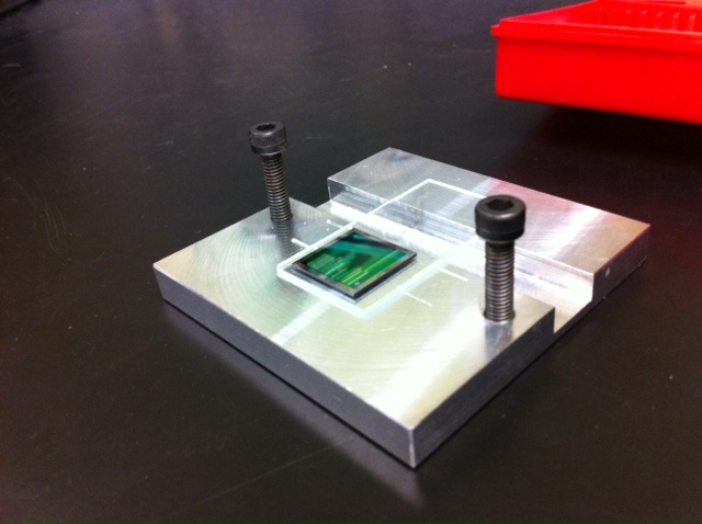 | The chip sits on a standard glass slide. The slide makes it easy to fine-tune the position of the chip. The slide also provides electrical isolation from the metal block. |
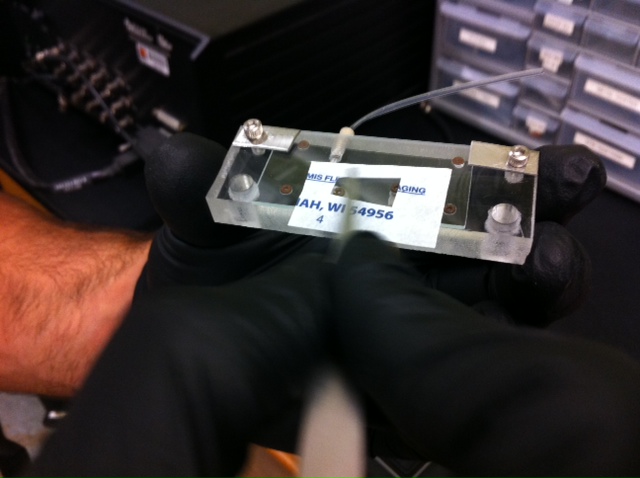 | The plexiglass block is designed to feed liquid onto the chip. The interface between the block and chip requires a glass slide with three holes (the holes align with the three o-rings) and a gasket. The glass slide with 3 holes is first positioned and gently clamped in place (silver screws on the corners). Then a gasket is fabricated out of parafilm. The parafilm is cut with a scalpel. The inside of the gasket is just big enough to frame the three holes. The parafilm is gently pressed onto the glass. The parafilm adheres well. The flap of extra parafilm is sliced off, using the edge of the glass as a guide for the scalpel. |
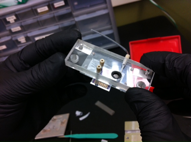 | The plexiglass block is now positioned over the chip and pressed onto the chip. A small amount of pressure is enough to stick the chip onto the parafilm. The photo shows that the chip can be picked up using the adhesion of the parafilm. Now the reference electrode must be placed in the large hole. The reference electrode should be squirted with DI water. A drip of water will collect on the tip of the reference electrode. Shake off the drip, but never let the tip of the reference electrode become dry. Hold the plexiglass piece off the table with fingers at the edges of the plexiglass. Press the reference electrode into the o-ring without disturbing the chip. |
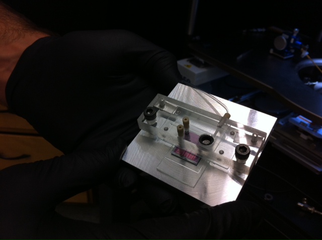 | Now the whole assembly can be secured onto the metal base using the pair of black machine screws. A small amount of pressure is required to make a water-tight seal between the chip and the parafilm. Make the screws finger tight. Don't crank down on the screws. Excessive pressure will snap the glass slides and/or the chip. Place the assembly on the chuck of the probe station. |
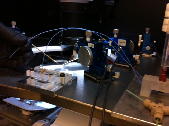 | Now the first microfluidic inlet line can be inserted. First, get the air bubbles out of the inlet line. Then push the line all the way down into the port. Note that the end of the line is cut at an angle, so you don't have to worry about closing off the flow. You should feel the inlet line pass through an o-ring. Tighten the tan colored screw to compress the o-ring. Now flood the system with the liquid from the first inlet line. Liquid will start to come out the second inlet line. This is good! You have now removed all the air bubbles from the system. |
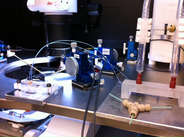 | Now the second inlet line can be inserted. Get the air bubbles out of the line. Push the line into the second inlet port. Tighten the screw. Now you are ready for pressure driven laminar flow. |

