This is an old revision of the document!
AFM Tip Change
It takes practice. Please practice with an old tip that no one cares about. The first image gives an overview of what you'll be looking at:
- Invert the AFM head (the tripod structure) onto the stabilization table. Remove the tip holder by pressing the black rubber button and secure it in the temporary mount by the laser.
- Loosen the middle screw that presses the clamp onto the tip. Use the correct Phillips screwdriver (the head of the screwdriver must fit the screw otherwise the screw will get stripped). Do not take out the screw completely because it is easy to loose. It is a standard right-handed screw (clockwise will tighten).
- Grab the old tip by its sides with a pair of tweezers and pull it away from the clamp. It should slide out freely.
- Remove a new cantilever from the box with a pair of tweezers using a twisting motion - be careful not to touch the end with the tip!
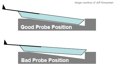
- Slide the tip between the tip holder and the clamp. The cantilever should be placed so it isn't inserted too far or too short. Too far, and the tip will not be well situated in the holder and zeroing the deflection will be impossible (see the figure below).
- Once the tip is inserted properly, tighten the clamp and replace the holder in the AFM head. Make sure to rotate the AFM head in the opposite direction you used to invert the head, to avoid twisting the head cable.
- Test the tip insertion two ways: i) Make sure the laser spot can be placed on the tip and the deflection can be zeroed without placing the wheels at their maximum range. ii) Auto tune the AFM, and make sure the amplitude and phase plots are free of any irregularities.
Tips and Tricks: The two images below show a tip that is pushed too far underneath the clamp, and a tip that isn't pushed far enough under the clamp. In these configurations, it took a drive amplitude of > 300 mV to get the tip to oscillate with 1 V amplitude. Moreover, the oscillation amplitude drifted by > 10% over a 10-minute time scale.
The image below shows a top-down view of a tip that is mounted correctly. It's a little crooked, but it still works fine. When this cantilever was tuned, the drive amplitude was less than 100 mV and the oscillation amplitude remained stable over the 10-minute time scale.
The image below shows a side-on view of a tip that is mounted correctly. The purple line (aligned with the tip) is parallel with the blue line (aligned with glass window).


